OrchidBox Universal Climate Control Board
Regular price
$32.99
Regular price
Sale price
$32.99
Unit price
per
Shipping calculated at checkout.
Couldn't load pickup availability
Climate Board - Modular Environmental Control System
Overview
The Climate Board is a versatile hardware interface platform designed for environmental monitoring and control applications. Built to work with Raspberry Pi and/or ESP32 microcontrollers, this board provides a robust foundation for automation projects ranging from greenhouse management to HVAC control systems.
Important: Components are NOT included with board-only product variants and must be purchased separately.
Key Features
Dual Microcontroller Support
- Flexible connectivity: Connect Raspberry Pi via ribbon cable and/or ESP32 simultaneously
- Redundant control: When both controllers are connected, RPi TX/RX communicates directly with ESP32
- Failsafe operation: ESP32 can maintain critical real-time control (pumps, safety systems) if RPi crashes or becomes unstable
- ESP32 compatibility: Designed for ESP-32-WROVER footprint (verify compatibility with your specific dev board using board layout)
Configurable Power Architecture
- Voltage source selection: Jumper-selectable power routing to SYS pin
-
5V options:
- Power from Raspberry Pi 5V output
- Power from auxiliary 5V jack
-
3.3V options:
- Power from Raspberry Pi 3.3V rail
- Power from ESP32 3.3V rail
- Auxiliary 5V power jack: Supplemental power header for ESP32 when RPi current capacity is insufficient
0-10V PWM Control Interface (OK0-OK4)
- Isolated optocoupled outputs: Industry-standard 0-10V control for fans, dimmable lights, and variable-speed equipment
- Signal only: Provides control signals without power (devices must be self-powered)
- Exposed control pins: Chain multiple devices to single control channels
- Required components: 47kΩ resistor required for each optocoupler used (slots R_S0 through R_S4)
3.3V Digital/Analog Outputs (4 channels)
- Raspberry Pi mode: Digital output only via GPIO pins
- ESP32 mode: True analog output capability
- 2-pin headers: Vout and GND per channel
- Pulldown resistor slots included
- Note: RPi requires PWM Expansion Board for true PWM output (see Expansion Boards section)
ADC Analog Input Channels
- Sensor compatibility: Designed for analog sensors (soil moisture, light levels, temperature, etc.)
- 3-pin configuration: +3.3V, Sense, and Ground
- Raspberry Pi: Uses ADS1015 ADC converter (not included)
- ESP32: Uses native ADC GPIO pins
- Pulldown resistor slots included
I²C Bus Infrastructure
- Non-multiplexed headers: Direct bus access with dedicated pin headers
- Multi-device support: Headers for up to 4 devices on primary bus
- Expansion ready: Compatible with I²C Multiplex expansion board for additional devices
Convenience Power Headers
- Multiple taps: 3.3V, GND, and 5V (when available) headers throughout board
- Quick prototyping: Easy power access for sensors and peripherals
Expansion Boards
I²C Multiplex Expansion
- Controller: TCA9548A I²C multiplexer
- Solves address conflicts: Connect multiple sensors with identical I²C addresses
- Reset capability: Dedicated reset pin (refer to pinout diagram)
- Clean signal routing: Eliminates bus contention issues
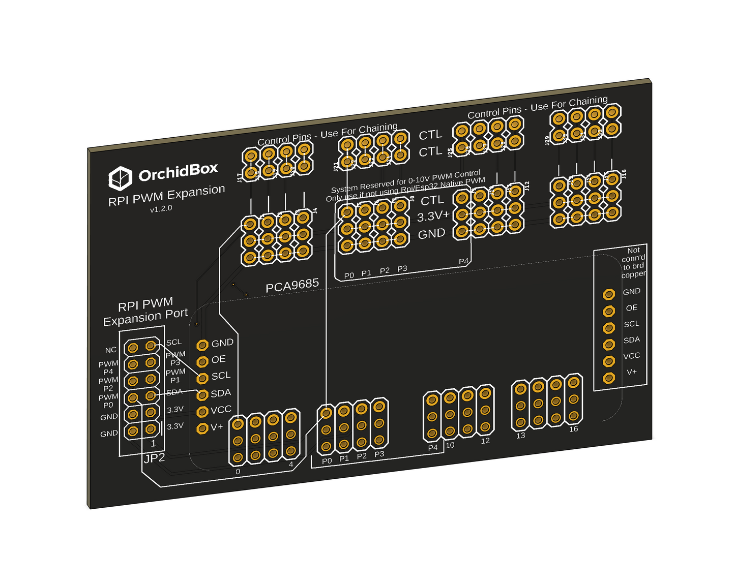
PWM Expansion Board
- 16-channel PWM: Expands to 16 independent PWM outputs
- Controller: PCA9685 I²C PWM driver
- Address configuration: Must be configured to 0x71 address to avoid conflicts
- Pre-wired channels: Channels 4-8 connected to nets PWM P0-P4
- Signal chaining: Pin headers support multiple devices per channel
- Critical for RPi: Raspberry Pi lacks reliable hardware PWM; this board provides stable PWM for both platforms
5V Logic Level Expansion
- Level shifting: Converts 3.3V logic to 5V output
- Controller: 74125N-5V quad buffer (not included with board-only variants)
-
Use cases:
- NeoPixel/WS2812B LED control
- 5V logic devices
- Industrial control interfaces
- Power note: Provides signal level only; high-current devices (LED strips) require independent power supply
- Pulldown resistor slots included
Technical Specifications
- Board power trace capacity: 400mA maximum
- Logic signal current: 100mA maximum per channel
- Operating voltage: 3.3V / 5V dual-rail
- I²C bus voltage: 3.3V
- ADC input range: 0-3.3V
- 0-10V control output: Optically isolated, signal only
Typical Applications
- Greenhouse environmental control
- Hydroponic system automation
- HVAC zone control
- Aquarium/aquaponics monitoring
- Indoor farming operations
- Laboratory environmental chambers
- Smart building automation
- Industrial process control
What's Included
Board-only variants include:
- Climate Board PCB with all traces and connection points
- Jumper configuration headers
- Resistor slots (resistors not included)
Components must be purchased separately:
- Microcontrollers (Raspberry Pi, ESP32)
- ADC chips (ADS1015)
- Expansion board ICs (TCA9548A, PCA9685, 74125N-5V)
- Resistors (47kΩ for optocouplers, pulldown resistors)
- Ribbon cables and connectors
- Sensors and controlled devices
Important Notes
- Verify ESP32 dev board footprint compatibility before purchase
- Configure PCA9685 to 0x71 address when using PWM expansion
- Install 47kΩ resistors in R_S0-R_S4 slots for optocoupler operation
- Observe maximum current ratings for reliable operation
- Refer to detailed pinout diagram for specific GPIO assignments
Climate Board Pinout Table
| Name | Net Name | ESP32 | RPI | Typical Use |
|---|---|---|---|---|
| GND | GND | GND | GND | - |
| RPI Ribbon | ||||
| ESP32 | ||||
| ESP32 IO0 | ESP32_IO0 | IO0 (used for FW flash) | 16 | |
| ESP32 EN | ESP32_EN | EN (used for FW flash) | 21 | |
| 3.3V* | OBOX-3.3V | 3.3V | 3.3V | - |
| 5V* | OBOX-5V | VIN pin / USB | 5V | - |
| 5V AUX | AUX5-V+ | |||
| PWR_SIG | PWR_SIG | 12 | GPIO 25 | Turns on NC relays |
| RPI_TX | RPI_TX | RX | TX | |
| RPI_RX | RPI_RX | TX | RX | |
| I2C | - | I2C1 | I2C1 | I2C multiplexer TCA9548A (optional) |
| SDA | I2C1-SDA | 21 | GPIO 2 | |
| SCL | I2C1-SCL | 22 | GPIO 3 | |
| I2C RESET | I2C_RESET | D1 (GPIO 8) | GPIO 20 | |
| 0-10V Control Outputs | ||||
| 0-10V #1 | PWM-P0 (controls S0) | 4 | PCA9685 Ch. 4 | Light W |
| 0-10V #2 | PWM-P1 | 15 | PCA9685 Ch. 5 | Light Y |
| 0-10V #3 | PWM-P2 | 18 | PCA9685 Ch. 6 | Light R |
| 0-10V #4 | PWM-P3 | 19 | PCA9685 Ch. 7 | Light G / Circ. Fan |
| 0-10V #5 | PWM-P4 | 23 | PCA9685 Ch. 8 | Light B |
| 3.3V Digital Inputs | ||||
| 3.3V Digital-In 1 | DIN-D0 | 16 | GPIO 17 | Bucket sense 1 |
| 3.3V Digital-In 2 | DIN-D1 | 17 | GPIO 27 | Bucket sense 2 |
| 3.3V Digital-In 3 | DIN-D2 | - | GPIO 22 | |
| 3.3V Digital-In 4 | DIN-D3 | - | GPIO 26 | |
| 3.3V Digital Outputs | ||||
| 3.3V Digital-Out 1 | D3V-D4 | 25 | GPIO 23 | Mist |
| 3.3V Digital-Out 2 | D3V-D5 | 26 | GPIO 9 | Rain |
| 3.3V Digital-Out 3 | D3V-D6 | 27 | GPIO 11 | Fog |
| 3.3V Digital-Out 4 | D3V-D7 | 5 | GPIO 5 | |
| 3.3V Digital-Out 5 | D3V-D8 | - | GPIO 6 | |
| 3.3V Digital-Out 6 | D3V-D9 | - | GPIO 24 | |
*Voltage sources are jumper-selectable. See configuration section for details.
Share